

This post originally appeared here on the GoDaddy Engineering blog.
The Over App is a playground for creating beautiful content for social media. As developers on the app, we are often inspired by the pictures and videos that our users make. To inspire our users a bit more, we decided to create a small easter egg in the app to add some delight for our LGBTQ+ community.
What started off as a comment “Hey, what if we animated this like a rainbow, that’d be cool!”, ended up shipping to users as a cute easter egg available in the app today.
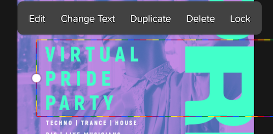
What is this Easter Egg then? If someone types the words “gay”, “pride”, “lgbt”, “lgbtq”, “lgbtq+”, “#pride2021” etc as content for a Text Layer, the text box outline changes into a magical animated rainbow. 😍
The Idea 💡
We were in the process of rewriting a bunch of our existing tooling to OpenGL and whilst doing this we realized the potential that this unlocked for us. Animations became a bit easier and our potential to draw (pretty much) anything was unlocked. When I first saw the animated bounding box (white and grey moving lines), I instantly thought of a Christmas candy cane (red and white moving lines) but after chatting with my colleague we thought that a rainbow would be even more exciting. We then decided the way we could incorporate this was to change the box based on the contents of the layer and turn it into a delightful little Easter egg.
We tried first with separate line segments to represent the rainbow:
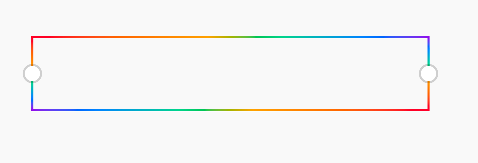
After getting some design input, we settled on a beautiful rainbow gradient look instead:
The Implementation ✏️
Hopefully at this point you are thinking: that looks cool, how did you do it? Well, buckle up for the explanation. If you want to see the final code it can be found here.
The box is rendered on screen using OpenGL and an Android SurfaceView that takes GL commands. There is a lot of set up to get OpenGL to render something on screen. If you are new to OpenGL, I have written a resources guide for learning OpenGL that you can find here, that’ll help with getting more familiar with OpenGL concepts.
This post is going to cover more of the specifics for how we render the rainbow bounding box gradient (and not so much the core concepts of OpenGL).
Drawing the rainbow bounding box 🌈
In order to use OpenGL on Android we need to do the following:
- Set up a SurfaceView and custom Renderer where we can invoke GL calls from
- Define GL Geometry for the bounding box
- Define GLSL Shader Program: Vertex Shader & Fragment Shader
- Bind the GL program, geometry and shader uniforms
- Invoke the “draw” operation
- Unbind the program and geometry
Rendering with OpenGL is quite unlike drawing on a Canvas. To get something on screen, you have to define your vertex
data and send it through the OpenGL pipeline.
This diagram describes what each step does in the pipeline.

We will be covering all these individual steps in this post.
1. SurfaceView setup
In order to use OpenGL, we need to use a GLSurfaceView. This is an Android view that provides a GL Context where we can call GL methods.
In our layout file, we include one as follows:
<?xml version="1.0" encoding="utf-8"?>
<android.opengl.GLSurfaceView
    xmlns:android="http://schemas.android.com/apk/res/android"
    xmlns:app="http://schemas.android.com/apk/res-auto"
    android:id="@+id/surface"
    android:layout_width="match_parent"
    android:layout_height="match_parent"/>
In the Activity, we need to set the renderer (our custom class that contains the GL class) and the requested OpenGL version:
val surfaceView = findViewById<GLSurfaceView>(R.id.surface)
// We use OpenGLES 3.0 because it has more features than 2.0
// It has a couple of nice newer features like - vertex array objects etc - more information [here](https://stackoverflow.com/a/38163130)
surfaceView.setEGLContextClientVersion(3)
surfaceView.setRenderer(RainbowBoxRenderer())
Our base renderer (without any drawing logic) looks as follows:
class RainbowBoxRenderer : GLSurfaceView.Renderer {

    override fun onSurfaceCreated(gl: GL10?, config: EGLConfig?){
        // run to create the surface
    }

    override fun onSurfaceChanged(gl: GL10?, width: Int, height: Int) {
        // run when the views width/height changes
    }

    override fun onDrawFrame(gl: GL10?) {
        // The function to draw the contents, run very often, avoid allocations in this function.
        // Similar to onDraw(canvas : Canvas) for CustomViews.
    }
}
We now have the shell required to draw the rainbow box!
2. Geometry for the outlined box
In order to draw anything in OpenGL, we need to provide geometry to the GPU to tell it where to draw (and the shape of what we will be drawing). Everything in OpenGL is made up of points, lines and triangles. In order to render a square, you need at least 2 triangles. For our outlined box, we need a bit more than just 2 triangles, since we don’t want a box, we want an outline of a box.
We are going to give GL the vertices for a typical box, but also give it a few more vertices to help us make an outlined box. In GL, there are only primitives, therefore to represent coordinates and other information, it’ll all need to be stored in the same array and we will inform GL of the stride length (ie the number of float values per vertex). To make a standard box, this is the geometry we would use:
// each line represents a "vertex" that GL will read. In this example there are 4 vertices to draw a square.
// The first two values represent X,Y coords. The second two represent the corresponding coordinates of a texture/bitmap that should be loaded up at that point.
val attributeValues = floatArrayOf(
            -1.0f, 1.0f, 0.0f, 1.0f,
            -1.0f, -1.0f, 0.0f, 0.0f,
            1.0f, 1.0f, 1.0f, 1.0f,
            1.0f, -1.0f, 1.0f, 0.0f
        )
You may notice that the coordinates are between -1 and 1, which is different from the Android coordinate system which goes from 0 to the size of the canvas. The center point for OpenGL is the center of the screen, whereas for Android this is at the top left corner. It does seem odd at first, but OpenGL is mostly used for 3D rendering and so having the center point at the center of the screen makes more sense. This documentation contains more information around OpenGL’s coordinate system.
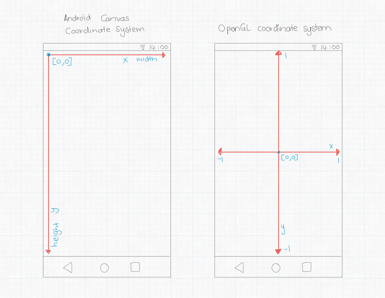
For our set up, we are including supplementary information on each vertex which will help us give the box a stroke width. The diagram below describes what our geometry will do:
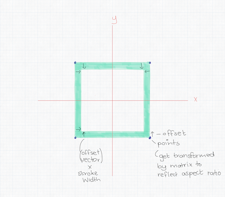
We will define the four coordinates of the box, similar to the ones shown above, but we will add some more information about how we want to draw an offset for a particular line.
Let’s define the outlined box geometry. We first provide the position of the vertex coordinate (x,y), then the offset vector (x,y) – that this point needs to be shifted in order to to form a line of non-zero thickness. Without this, the geometry would have no thickness and wouldn’t draw anything.
The progress variable represents the side of the box. Each side is 0.25 in “length”, with total length being 1.0. This is used later for calculations of the aspect ratio and moving the gradient along the perimeter.
The last 3 values in each line are for padding the array. OpenGL prefers when data is aligned by 4xN, N being the data size. We pad our array with 3 more 0f values at the end of each stride to adhere to this best practice. For more information about this particular quirk, this blog post covers the topic.
val o = 1.0f
val attributeValues = floatArrayOf(
    //position   offset       progress  padding
    -o, o,       -o, 0.0f,    0.0f, 0f, 0f, 0f, // 1
    -o, o,        0.0f, 0.0f, 0.0f, 0f, 0f, 0f,// 2
    -o, -o,      -o, 0.0f,    0.25f,0f, 0f, 0f, // 3
    -o, -o,       0.0f, 0.0f, 0.25f,0f, 0f, 0f, // 4
    -o, -o,      -o, -o,      0.25f,0f, 0f, 0f, // 5
    -o, -o,       0.0f, -o,   0.25f,0f, 0f, 0f, // 6
    -o, -o,       0.0f, 0.0f, 0.25f,0f, 0f, 0f, // 7 (4)
    o, -o,        0.0f, -o,   0.5f,0f, 0f, 0f, // 8
    o, -o,        0.0f, 0.0f, 0.5f,0f, 0f, 0f, // 9
    o, -o,        o, -o,      0.5f,0f, 0f, 0f,// 10
    o, -o,        o, 0.0f,    0.5f,0f, 0f, 0f, // 11
    o, -o,        0.0f, 0.0f, 0.5f,0f, 0f, 0f, // 12 (9)
    o, o,         o, 0.0f,    0.75f,0f, 0f, 0f, // 13
    o, o,         0.0f, 0.0f, 0.75f,0f, 0f, 0f, // 14
    o, o,         o, o,       0.75f, 0f, 0f, 0f,// 15
    o, o,         0.0f, o,    0.75f,0f, 0f, 0f, // 16
    o, o,         0.0f, 0.0f, 0.75f,0f, 0f, 0f, // 17 (14)
    -o, o,        0.0f, o,    1.0f,0f, 0f, 0f, // 18
    -o, o,        0.0f, 0.0f, 1.0f, 0f, 0f, 0f,// 19 (2)
    -o, o,       -o, o,       0.0f, 0f, 0f, 0f,// 20
    -o, o,       -o, 0.0f,    0.0f, 0f, 0f, 0f// 21 (1)
)
The geometry we create will be sent into the Vertex Shader that we will define later in step 3. The usage of this geometry is set up in our helper classes called RectOutlineVao and RectOutlineBuffer.
For the details of how to bind the geometry and set it up with OpenGL, see the code sample linked above.
3. GLSL Shader Program: Vertex Shader + Fragment Shader
A shader is a piece of code that runs on the GPU. It is written in GLSL Shading Language and runs in parallel for each pixel or input vertex.
There are two different types of shaders that are required to draw anything on screen: a vertex shader and a fragment shader.
Vertex Shader
A vertex shader is a shader that runs for all vertices that are sent through from the geometry set up we did in point 2. In this shader, we ensure that the aspect ratio of the box we want to draw is also taken care of in the output point.
A vertex shader’s goal is to set the gl_Position (and any other additional out values we want) required by the fragment shader. Although this will only run for each vertex from the geometry defined above, OpenGL interpolates between the vertices created by this shader and the fragment shader is run for all pixels in between. This process of the pipeline is called Rasterization.
#version 300 es
precision highp float;
precision highp int;

uniform highp mat4 uModelMatrix;
uniform highp mat4 uViewProjMatrix;
uniform highp float uStrokeWidth;
uniform highp float uAspectRatio;

layout (location = 0) in vec2 aPosition;

// Offset represents the direction in which this point should be shifted to form the border
layout (location = 1) in vec2 aOffset;

// Progress changes from 0.0 to 1.0 along the perimeter (does not account for scaling, not yet).
layout (location = 2) in float aProgress;

out float vProgress;

// This version of normalize() 'correctly' handles zero-length vectors
vec2 safeNormalize(vec2 v) {
    if (length(v) == 0.0) return v;
    return normalize(v);
}

void main() {
    float aspectRatio = uAspectRatio;
    vProgress = aProgress;
    vec4 worldPosition = uModelMatrix * vec4(aPosition, 0.0, 1.0);

    // We need to get the correct direction for the offset that forms the border (the thickness of the bounding box).
    // For that we see where the point ends up in the 'world' coordinates, then correct by aspect ratio to account for scaling,
    // and then normalize. Ta-da, offset direction!
    vec4 offsetPosition = uModelMatrix * vec4(aPosition + aOffset, 0.0, 1.0);
    vec2 difference = offsetPosition.xy - worldPosition.xy;
    vec4 offset = vec4(safeNormalize(difference) * uStrokeWidth, 0.0, 0.0);
    gl_Position = uViewProjMatrix * (worldPosition + offset);
}
Fragment Shader
A fragment shader is the GLSL code that produces the color of the pixel that should be displayed on screen at a particular point. This piece of code is run in parallel on the GPU, it is highly performant because of this, and can execute very quickly.
Below is the fragment shader for the rainbow outlined box. The output of the shader is to set the single pixel’s color by setting the oColor to the calculated color for that individual pixel. We use the uTimeOffset to perform the animation. The rest of the logic inside this shader is performing the calculation for the color that should be displayed. We could just as well have set the color to black oColor = vec4(vec3(0), 1.0f); and have a black outline drawn instead.
#version 300 es

precision highp float;

uniform highp float uAspectRatio;
uniform highp float uDashCount;
uniform highp float uTimeOffset;

in highp float vProgress;

const vec4 COLORS[7] = vec4[](
    vec4(1.0000, 0.1490, 0.2196, 1.0),
    vec4(1.0000, 0.4196, 0.1882, 1.0),
    vec4(1.0000, 0.6353, 0.0078, 1.0),
    vec4(0.0078, 0.8157, 0.5686, 1.0),
    vec4(0.0039, 0.5020, 0.9843, 1.0),
    vec4(0.4824, 0.2118, 0.8549, 1.0),
    vec4(1.0000, 0.1490, 0.2196, 1.0) // Re-adding the first color to avoid mod() operation after 'colorIndex + 1'
    );

out vec4 oColor;

void main() {
    // vProgress is interpolated between 0 - 1 by the vertex shader.
    // We multiply by uTimeOffset to give the animation over time.
    // We multiply uTimeOffset by 16 to make the speed of the animation a bit faster, and 0.125 to stretch out the gradient a bit more.
    float progress = (vProgress + uTimeOffset * 16.0) * 0.125;
    float colorIndex = mod(uDashCount * progress / 4.0, 6.0); // There are actually 6 colors, not 7
    vec4 currentColor = COLORS[int(floor(colorIndex))];
    vec4 nextColor = COLORS[int(floor(colorIndex)) + 1];
    // The output color of the pixel is a mix between the two colors, producing the gradient effect
    oColor = mix(currentColor, nextColor, fract(colorIndex));
}
For more detail around how the aspect ratio is handled for the box – take a look at the sample code that does the calculation using vProgress to ensure its not stretched. The above is a simplified version of it.
ShaderProgram
Now that we have our two GLSL shaders defined. We need a way to tell OpenGL of their existence and that we would like to use them.
We’ve created a wrapper class that takes care of this and the corresponding GL code that needs to run in order to compile the shaders, link them and functions to bind and unbind them. Since its mostly boilerplate code, we’ve excluded it for brevity. The code for ShaderProgram can be found here.
4. Binding the GL program, geometry and shader uniforms
In the onDrawFrame function of our custom renderer, we first reset the background color to white. We then call setupMatrices(), and then bind the geometry, call bind on the shaderProgram, and then bind the uniforms:
glClearColor(1.0f, 1.0f, 1.0f, 1.0f)
glClear(GL_COLOR_BUFFER_BIT)

setupMatrices()

// bind geometry
rectOutlineVao.bind()
// bind shader
shaderProgram.bind()
shaderProgram.bindUniforms(aspectRatio, modelMatrix, viewProjMatrix)
After this point, we are ready to call draw.
5. Invoke the “draw” operation
In the onDrawFrame function (after the previous step), we call glDrawArrays:
glDrawArrays(GL_TRIANGLE_STRIP, 0, rectOutlineVao.vertexCount())This function invokes the bound shaders and bound geometry, runs through the vertex shader, and then the fragment shader, to decide what pixels to draw on screen at what position.
6. Unbind the program and geometry
In the onDraw function after calling glDrawArrays, we need to unbind the geometry and shader program:
 // unbind shader
shaderProgram.unbind()
// unbind geometry
rectOutlineVao.unbind()
This cleans up our execution, and resets the GL threads state back to what it was before running our code.
Finally 🌈
We now have a beautiful animated rainbow box drawing on screen:
Yay! That was a lot to process 😱 OpenGL can be pretty crazy! If you would like to see the full working example – it can be found here: Github OpenGL Rainbow Box Sample.
At GoDaddy everyone is welcome, we strongly believe that diverse teams build better products. We love having representation from all different groups. So for pride month, we are highlighting the GoDaddy United (LGBQT+) group, which is designed to ensure that within the walls of our company, everyone is able to be themselves, feels safe and is informed with regard to issues relating to the Lesbian, Gay, Bisexual, Transgender and Queer communities. For more information about this and other initiatives – head to our website here.
We love adding little bits of user delight and we hope this puts a bit of a smile on people’s faces when they encounter it in the app.
If you have any questions or feedback, feel free to reach out to me on Twitter @riggaroo!